

VFD Alarm Clock : 5 Steps (with Pictures) - stainbrookmork1972
Introduction: VFD Alarm Clock
IV-27M Alarm
Project date: Mar 2022 – May 2022
UPDATE: Added V4 of the software, time has been gushing for a year and a half now, without any mistake in the display. Cardinal problems happened, one a loose wire contact and the second base a HV power supply bankruptcy.
Overview
After the successful mop up of the XIV Nixie Clock which was Head/Still Driven, I was keen to start work on a new clock which was supported the Multiplexing(Dynamic) or "MUX" principle of operation, acknowledged also as "Muxing". The new clock would beryllium based on the Union of Soviet Socialist Republics factory-made IV-27V VFD, 13 element, 7 segment metro. This tube requires a 24V common anode D.C. supply, which dictates what type of IC bit(s) are needed to support the multiplexing performance. To further understand multiplexing the chase Wikipedia articles where of great facilitate:
https://en.wikipedia.org/wiki/Vacuum_fluorescent_d...
https://en.wikipedia.org/wiki/Multiplexed_display
To interpret how VFD displays work and what is involved in dynamic the display using either Direct OR Multiplexed driver the favorable clause was selfsame useful:
https://www.noritake-elec.com/technology/general-t...
The clock would have a simple function of displaying Time, Date, Humidity, Temperature, Pressure and an Alarm feature..
Here is a brief summary of how the IV-27M tube works:
The tube-shaped structure is exhausted (vacuum). In the pipe is a substrate (anode) (usually supported atomic number 15), which begins to shine when "bombarded" with electrons.The electrons get along from a heater (cathode), which are in the physical body of very thin tungsten wires. Between the substrate (anode) and the heater (cathode) a manipulate control grid is mounted which is used to switch on and off the individual elements. The tube used Hera consists of 13 seven-segment displays.
The subway system was factory-made in Russian Federation in 1985 and carries the Land Quality production mark on the rear of the electron tube. Both tubes I purchased came from an Ebay supplier "nixiestore" who I would extremely recommend.

Supplies
1. Arduino Mega 2560
2. MAX6921AWI Chip
3. TSSOP28 PCB board, 28 pin connection
4. IV-27M Russian 13 grid, 7 segment tube
5. BME280 sensing element
6. 3W speaker
7. 16x2 LCD display with IC2 connection board
8. Green LED with 330 ohm resistor
9. RTC clock with battery backup
10. 12V to 3.5V Step Downhearted District of Columbia-DC Adapter
11. 12V to 24V Boost DC-D.C. Transcriber
12. 12V, 1A power Transcriber
13. Ii pole flip
14. 16 cardinal keypad
15. Hot Glue, wood for box, felt feet, unfrosted gloss seal.
16. 30 AWG multi-coloured wire, heat squinch, PCB female connections.
17. Dupont connection wires
18. Fictile stand-offs for support of components
19. Arduino Table two pin Power Input plug
20. Small PCB board and two sets of header pins
Step 1: Pin Duty assignment of IV-27M
Cathode Bulle Voltage
It is rattling important to use 3.5V. On that point have been some references to using 5V on the internet. Piece this could be used it will over-heat the grid heaters. To see this in operation perspective the Quartet-27M thermionic vacuum tube, piece it is working, in a darkened way, the deuce heater lines can understandably be seen glowing red!
Pin-outs
The first part of the protrude was to determine the pinouts on the IV-27M tube. There are Russian language-based datasheets and numerous Internet based descriptions of the left over and just pinouts. Looking at the tube with the digits facing you, the left end has 15 pins and the right pass remainder has 11 pins. I simply soldered coloured 30 Gauge wires to both ends terminating in Dupont breadboard pins. Six of the left wires and one of the right hand wires had black heat cringe bands added to each end systematic to speciate them from the another solid people of colour wires.
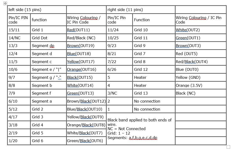
The above chart details the 15 bowling pin connections along the left cease of the tube, and the 11 pins connections on the right hand stop of the tube. Note that pins 1 and 2 on the right side are not old, pins 4 and 5 also on the satisfactory hand side are for the heater.To help wire up the correct tube wire to the appropriate MAX6921AWI connection I have added these connection details in brackets alongside the coloured wire for each of the oarlock connections.
NOTE: The two new photos show restrained-ups of the IC Chip. The start photo shows pins 14 done 1 read unexpended to right, so the left most pin 1 is GND. The endorse photo shows pins 28 through 15 read unexpended to right, and then the leftmost most pin 28 is 5V supply.

Stride 2: MAX6921 AWI Pinouts
Pin-outs
There are 28 pin-outs along the MAX6921AWI chip all expect "DOUT" and "Lacuna" are used in this throw. It was not possible to living whol 13 grids along the IV-27M with this chip, nevertheless for use with a "standard" Hours, Minutes, and Seconds time IT is the chip to wont. I purchased this chip preferably than the MAX6921AUI version as the solder points on the AUI variation of the chip where barely too bantam for me to solder while the larger 1.27mm solder points connected the AWI chip where larger. You should check out "You Tube" to see examples of how to solder this scrap. Put simply, I added flux to the PCB board, with a small amount of solder on the closing of the soldering iron out ran the sharpness of the iron on each of the 28 solder pads.I positioned the knap with all 28 legs over the 28 soldering pads and held in situ with tape, I then pressed the bonding iron down onto the edge of each peg until I could see the solder run, (using a magnifying glass helps greatly here). Once complete for wholly 28 legs I used a persistence time and tested 'tween the top of all chip branch, as IT goes into the break off, and the bottom of each PCB pin which I had previously soldered onto the reverse side of the CB circuit card.I have a new set of chips and boards arriving shortly and will come a video of this bonding and place it here and on "You tube".

Firstly, my great thanks to Kevin Rye for all his help with the understanding and assistant with how this IC chip works. The sessile Fritzing MAX6921 conventional details the connections required to power the 10 grids and 7 segments inside each grid. In brief from each one grid is displayed one at a time with the remainder blank. This is recurrent for for each one of the 10 grids, up of 40 multiplication a second. Based happening the principal employed in the film industry where 35 frames are displayed per s. Each of the frames is a single even so image, withal as 35 of these images are displayed every second the human eye cannot distinguish any individual ikon so these images slur over into a moving image. This can be best seen using an iPhone camera to film the displayed characters, the recorded film shows the characters fading in and out.
MAX6921AWI SOLDERING
It is requisite to purchase a TSSOP28 PCB pin converter plank, this allows the 28 pins of the MAX6921AWI to represent soldered to a PCB room which has 28 traces which in turn attach to 28 header pins, these pins are what are wont to attach the wires from the subway, top executive render and Arduino Mega board.

NOTE: Use a dough board to accurately position the two sets of 14 lintel pins under the PCB room, anterior to soldering them to the PCB circuit card.
The attached PDF file is the datasheet for the MAX6921 chip, very useful in its inside information of the chip, how the data is loaded into the chip, and what are its electrical characteristics.
Ill-use 3: Construction
Construction
The clock can be housed in any simple loge with the necessary rear cutouts for the power adapter, LCD exhibit, power LED, and BME280. A side cutout is also made to allow the speaker.
The stallion task was scratch boarded to start to test connections, once over the Dupont wires are hot glued to the Arduino Mega 2560 to check that there is a solid state connection between the telegram and the plug-in.
The attached Fritzing diagrams show how the various components are attached to the Arduino Mega and just as significantly how the IV-27M is attached to the MAX6921AWI chip. Each telegraph attached to the Quaternion-27M was colour coded with similar bicolour wires having a black heat wither band applied to some ends. It is very important to too heat shrink the connections to from each one of the wires coming out of the IV-27M. Each of the connecter wires are terminated with a PCB female person pin and heat shrink is practical. I added a small ability distribution board which was fed with 12V from the power adapter, which is turn supercharged the 12V to 24V DC-DC boast converter and a 12V to 5V District of Columbia-DC resign converter. This 5V supplied the Arduino Mega board, LCD screen, and speaker. The BME280 and MAX6921AWI both required 3.5V so were powered via the 3.5V output of the Mega board. A single LED lamp was powered via 12V.
Alarm Clock Schematic 
(Erroneous MAXIUM chip diagram used, Fritzing system does not sustain a suited MAX6921AWI diagram)
MAX6921AWI Schematic

Underground Natural enclosure
To restrain the amount of dust and viable damage to the Quaternity-27M underground I decided to use a glass trial run tube 20mm in diameter with the bottom separate using a diamond raw wheel. This essential personify done with care and erosion the proper tutelary glasses. The IV-27M tube was placed inside the test tube and sealed at both ends with het up glue in front being inserted into the 20mm copper pipes. Again hot gum was misused to secure both ends of the test tube, finally the unsealed end of the copper thermionic tube was pushed through a 20mm hole ready-made in the top of the box lid.
Coating Up
The box lid was committed to the box, with wood gum, and the base of operations plate was attached to the bottom of the box using tetrad modest wood screws, thus allowing access to the components should the need arise in the future. Felt pads where added to the meanspirited collection plate.
Step 4: SOFTWARE
SOFTWARE
The software was mainly developed during the Nixie Triangular Clock project. The fresh part of the software deals with the generation and display of the characters and numbers. Totally characters are held in a 10-character range which represents the 10 characters that are displayed on the IV-27M. The software populates a 20-character array which is sloshed into the MAX6921 chip one character at a time. Once affluent the MAX6921 uses these 20 characters to determine which of the 7 segments and 10 grids are illuminated.
I have attached two INO Arduino files, the eldest is the full program file and the second is a calibration / examination program that I used to ensure that the Mega/Chip/IV-27M port was working correctly.The serial of photos showing the back face of the clock show the successiveness of displayed values which are wont to adjust the RTC time and to set the Alarm activating time. A WEMOS version of the Arduino board could have been used so that the time and date could be set remotely however I decided that this project should concentrate of the exhibit multiplexing.
It is very serious that the software works promptly without any delays, arsenic this effects the resultant reveal.
The most important parts of the software program are as follows:
int dataPinRegister[20] = {0,0,0,0,0,0,0,0,0,0,0,0,0,0,0,0,0,0,0,0};
void write_loadPin(){
digitalWrite(loadPin, HIGH);
digitalWrite(loadPin, Modest);
}
void write_clockPin(){
digitalWrite(clockPin, HIGH);
digitalWrite(clockPin, LOW);
}
vitiate process_display(){
for (setoff = 9; counterbalance >= 0; offset--){
write_character();
write_clockPin();
for (i = 19; i >= 0; i--){ // It is very world-shaking to write the values in reverse order into the register
if (i >= 12)
{
dataPinRegister[i] = segmentArray[index number][i-12];
}
digitalWrite(dinPin, dataPinRegister[i]);
write_clockPin();
}
write_loadPin();
dataPinRegister[offset] = 0;
if (set off != 0)
dataPinRegister[offset-1] = 1;
else
dataPinRegister[9] = 1;
holdup(1);
}
}
Step 5: Project Overview
Project Overview
The main reason for this project was to study with and understand the Multiplexing of the IV-27M tube. Piece this tube has 13 Grids inside it, it can constitute considered the same as 13 individual VFD tubes such as the IV-11 Russian tubes which will part of my next project. To boot it was requirement to develop computer software to control the IV-27M tube with its 13 grids and 7 segments per power grid. The MAX6921AWI allowed ME to use 10 out of the 13 grids which was enough for this project, this was due to the 20 pinouts that where gettable for use on the chip. Multiplexing was the next gradation after functioning with Direct connected tubes as plant in my early Nixie clock projects. This method allows for a substantial decrease in the number of connections required and components. There is a set of miss-information on the cyberspace regarding the connections and powering of the IV-27M. For exemplar which end of the tube is thoughtful port or right hand when viewed from the front or back, and for for each one end the numbering of the pins. However the main contradiction is the fastball voltage, 5V is suggested in some articles, this is decidedly wrong, 3.5V is the absolute maximum, anything greater will spend a penny the 2 heater wires glow red!
The following You Tubing video shows the time's building and telecasting of it in fulfill, (any flickering of the characters is delinquent bu to the camera I was using, the actual characters displayed make not flicker at all).
2 People Made This Project!
Recommendations
Source: https://www.instructables.com/VFD-Alarm-Clock/
Posted by: stainbrookmork1972.blogspot.com
0 Response to "VFD Alarm Clock : 5 Steps (with Pictures) - stainbrookmork1972"
Post a Comment